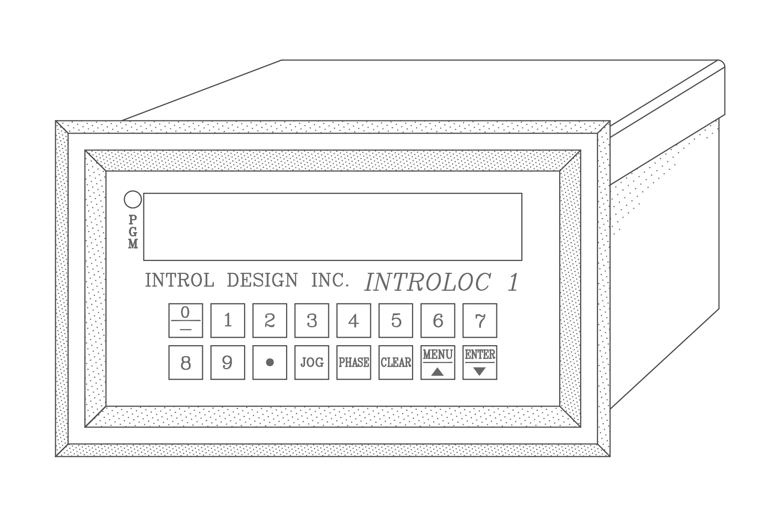
Interloc 1 (Model 601)
Through years of controlling speed and synchronizing with our earlier controls, we identified the need in the market for a sophisticated, yet simple to operate and understand controller. The Introloc 1 is a 6 decade, high resolution speed controller and position synchronizer designed, developed, and manufactured by Introl Design, Inc. This device permits 8 set points to be programmed and recalled via external inputs, plus one preset for on demand control. The unit allows unidirectional and bidirectional speed control, ratioed follower, and positional synchronization. This unit is fully programmable on the fly through the front panel keypad or through multidrop RS422/485 serial port. The Introloc 1, with its isolated inputs and isolated reference output, will interface with virtually every type of variable speed drive to allow a multi-axis control environment. The display can be programmed to display speed, ratio (lay), or phase shift. There are no pots to adjust, no jumpers to modify, everything is programmable for ease of set-up, replacement, and reducing down time. Two level programmable security is provided to limit unauthorized access through the front panel keypad. The Introloc 1 will accept single and dual channel quadrature type encoder signals as a reference and feedback, as well as magnetic pickups and AC tachs.

Products Features
SPEED CONTROLLER MODE
In this mode, the Introloc 1 will control and regulate the precise speed of one motor by constantly monitoring speed from either an incremental encoder or magnetic pickup. The feedback frequency is then compared by the internally generated ramped reference, to develop an error. The resultant error is passed through programmable error limits and then through the enhanced digital PID loop. The result of the PID loop is then summed with the feedforward and converted to a bipolar analog signal, then passed through ground isolation circuitry to provide an easy and trouble free interface to all types of variable speed drives.
FOLLOWER AND SYNCHRONIZER MODES
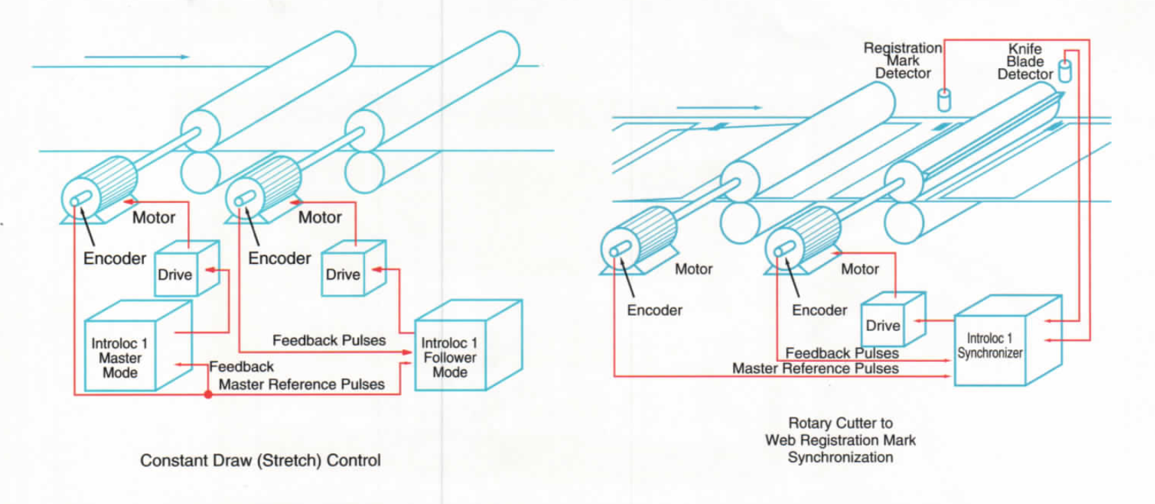
In the follower mode, the Introloc 1 basically works the same as the speed mode, with the exception that speed reference pulses are generated externally rather than internally. The Introloc 1 scales the received reference pulses by the programmed ratio and scaling factors, then compares them with the feedback pulses to develop error. The Introloc 1 will follow the master reference pulses at exact set ratio and perfect synchronization in both directions, with zero following and accumulative error.
The Introloc 1 can also accept positional signals from a proximity switch or marker pulse of an encoder, for “keyway to keyway”, or product synchronization and automatic position match, resulting in a low cost electronic line shaft or gearbox. The Introloc 1 can constantly monitor master and slave position and compensate for any product inconsistency in spacing. In situations where the follower drive is stopped and restarted with the master operating at line speed, the Introloc 1 can start the motor and reach synch speed smoothly.

Applications
- Precision speed control metering pumps, extruders, conveyors, etc.
- Accurate proportional speed follower winder traverse, printing presses, assembly and packaging lines, transfer conveyors, and takeaways.
- Excellent synchronizer registration mark synchronization of multi-color printing presses, rotary cutters, fillers, baking machinery, assembly and packaging lines.
Specification
- Input power: 115/230 vac ±15% or 12 to 15 vdc, 10 Watt max.
- Serial interface: RS422/RS485/RS232, 300 to 4800 baud to control and program
- Control options:
- Speed regulator
- Ratioed follower and inverse ratio mode
- Follower with position synchronization
- Response: 10 millisecond control loop for PID and feedforward. (1 millisecond optional.)
- Tuning: (PID) Separately programmable gain, integral, rate, and error correction factor to achieve stability and response, with separately programmable feedforward response.
- Operating Temperature: 0° to 55°C (32° to 131° F)
- Humidity: 0 to 90% non-condensing
- Presets: Speed/ratio, jog, manual set point, 8 programmable set points, 6 decade programmable 0.000001 to 999,999. Not to exceed 50 kHz feedback frequency.
- Acceleration: 0 to 600 seconds. Ramp disable input will stop ramp and maintain the velocity at which the slave was running.
- Deceleration: same as above, separately programmed.
- Inputs: Reference and feedback, 0 to 50 kHz single or dual channel, quadrature type, zero crossing magnetic pickup or open collector proximity or encoder.
- Position sensing device – open collector proximity or encoder reference pulse (channel Z or marker), 0 to 50 Hz.
- Control inputs: 7 inputs optically isolated 5 to 15 vdc, run/stop, jog, fwd/rev, memory, hold, inc, dec.
- Status outputs: Ramp done (at speed), zero speed. Open collector 50 mA at 24 vdc.
- Analog output: 0 to ±10 vdc, 12 bit resolution isolated or 0 to ±20 vdc.
- Output power: ±5 vdc at 500 mA used for master and slave encoder power. 10 to 15 vdc non-regulated at 100 mA used for proximity pickups.
- Display: 8 decade 0.6″ height, bright red modified alpha numeric LED display for programming, and speed, ratio, or phase readout.
- Physical Dimensions: 5.375″W x 3″H x 7.35″D
- Bezel Size: 6.625″W x 4″H
- Construction: Steel enclosure with cast aluminum bezel and unpluggable terminal blocks.

